Control Valve
Product Description
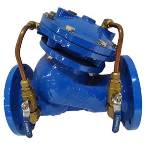
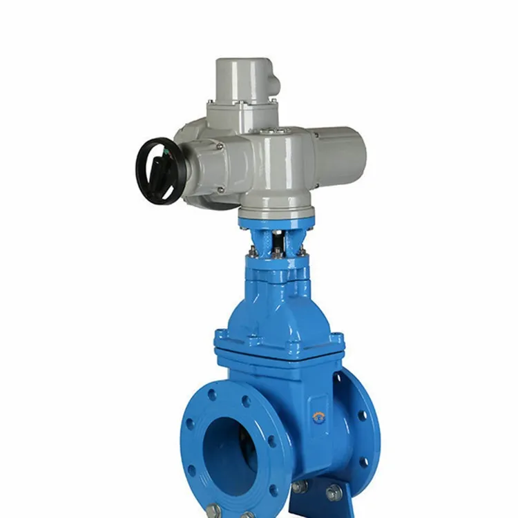
Multifunctional pump control valve consists of main valve and regulating valve and receiver system, the valve body adopts DC type valve body, the main valve control chamber is diaphragm type or piston type double control chamber structure, the control chamber is increased by one than the general hydraulic control valve, which increases the control function of the main valve and realizes the multi-functional control of the pump outlet such as slow opening, full opening, slow closing and stopping, which realizes the multi-functional control of the pump outlet by a single valve and a single adjustment. Multifunctional control.
This product is used in high-rise building water supply system and other water supply system pump outlet pipeline, to prevent and attenuate the pump start and stop the pipeline of water hammer, prevent water backflow to protect the pump, maintain pipeline safety. In order to realize the automation of pump operation, simplify management, reduce labor, improve reliability, people use hydraulic valves and electric valves to replace manual valves, a number of technical improvements to the monoblock valves, the emergence of slow-opening and slow-closing backstop valves, slow-acting open and close hydraulic valves, automatic slow-closing gate valves, double-speed self-closing valves and other new types of valves.
Product Detail Drawing
Product Basic Functions
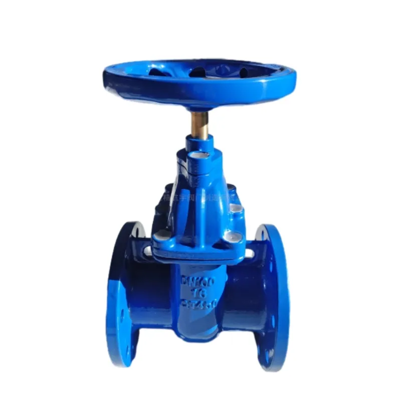
Gate Valve
The gate valve is usually in a closed state, the gate valve is slowly opened when the pump is started, and when the pump is stopped, the gate valve is quickly closed first, and then slowly closed after a certain degree. Closed gate start and closed gate stopping of the pump, can effectively prevent the opening of the pump water hammer and stop the pump water hammer, at the same time, reduce the motor load when the pump starts, the pump at zero flow rate when the minimum shaft power, generally only 30% of the design shaft power. Another function of the gate valve is that when the gate valve is closed, it can provide safe access conditions for valves and pumps such as backstop valves and pumps installed between the gate valve and the pump, preventing the return of water from the pressure pipe.
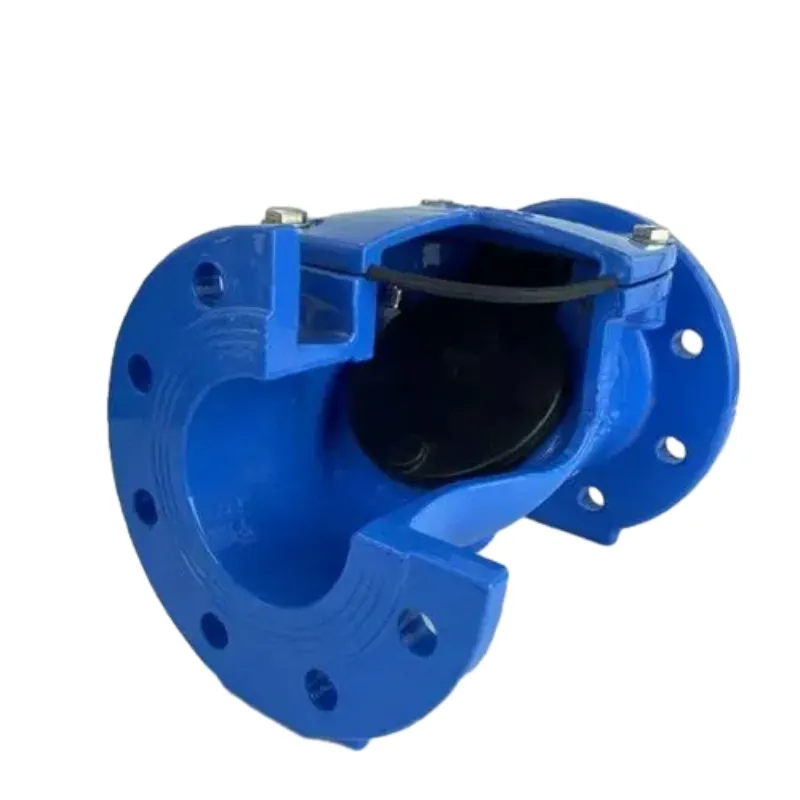
Check Valve
The check valve prevents the flow of water caused by a sudden power failure from changing direction and prevents backflow. Sudden shutdown of the pump is prone to water hammer. When the geometric head height of the pump is large, the instantaneous high pressure of severe water hammer can lead to pipe rupture and serious production accidents.
Water Hammer Eliminator
Water hammer eliminator can effectively eliminate all types of fluids in the transmission system without the need to stop the flow of fluids in the case of irregular water hammer and surge in the transmission system may produce water shock wave shock, so as to achieve the elimination of destructive shock waves, play a protective purpose. So in order to prevent water hammer on the transmission pipeline damage method, often in the pump pressure water pipe installed on the water hammer eliminator.
Principles of Construction
Working Principle
(1) When the pump is stopped, the valve plate is closed at the outlet end and the upper chamber of the diaxphragm under static pressure.
(2) When the pump starts, the water pressure is transmitted into the lower chamber from the bypass pipe, and the main valve plate and the slow closing valve plate open slowly under the water pressure at the inlet end and the lower chamber.
(3) Under the pressure of the inlet end, the valve plate rises to the maximum opening state, the opening height is determined by the flow rate.
(4) The moment the pump stops, the flow rate and pressure are suddenly reduced, and the main valve plate starts to slide down under the action of gravity.
(5) When the flow rate is close to zero, the main valve is closed, the main valve plate is left on the relief holes to weaken the impact of water hammer; the main valve plate on the formation of the pressure difference between the lower and upper, the valve outlet water pressure from the bypass pipe into the upper cavity to promote the diaphragm pressure plate, so that the lower cavity water discharged into the valve inlet, the slow-closing valve plate began to slow down the closure.
(6) slow closing valve plate completely close the drain hole, the valve back to the initial state of the pump.
Basic structure
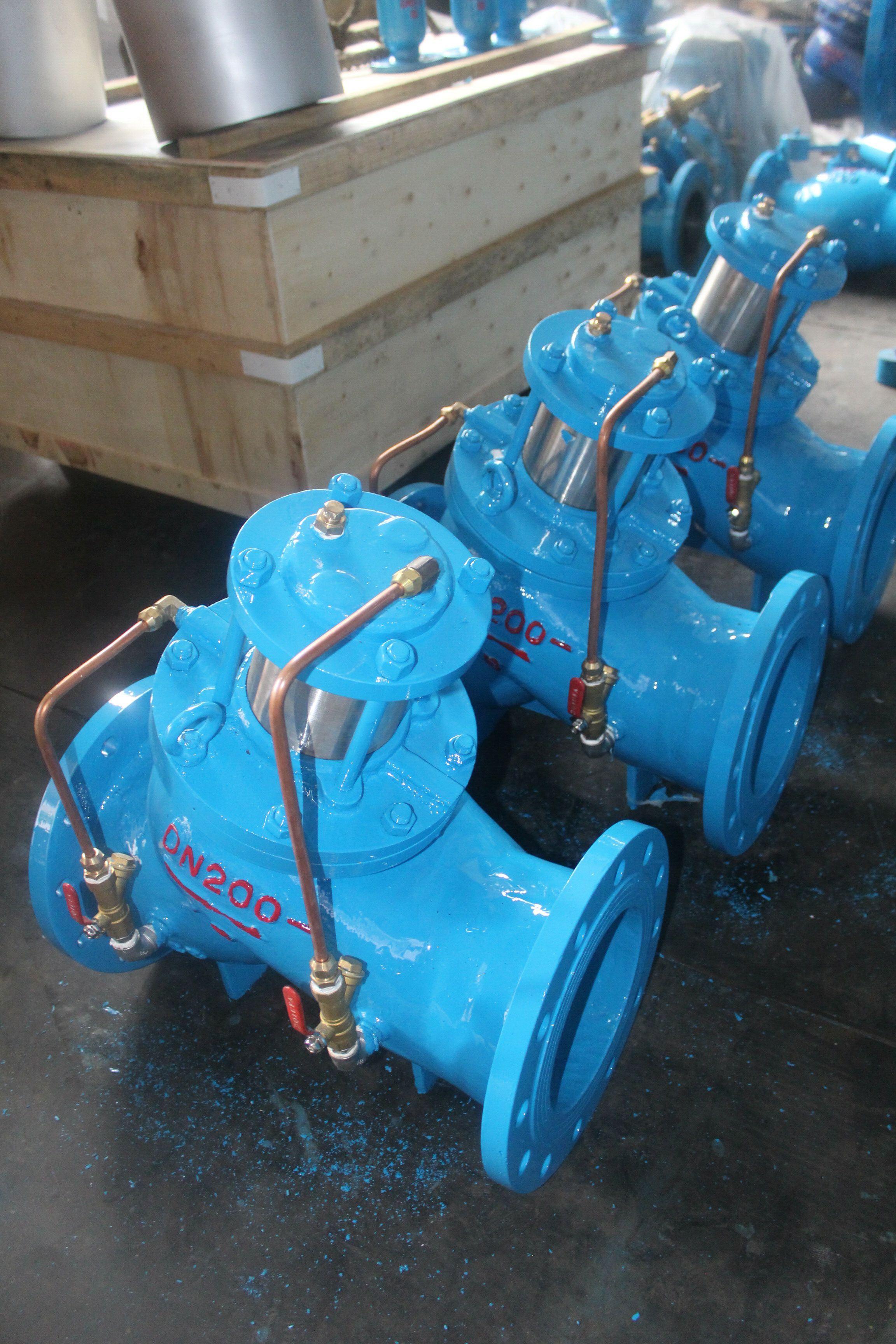
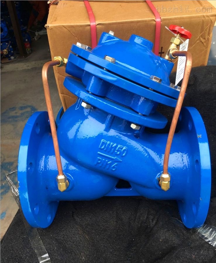
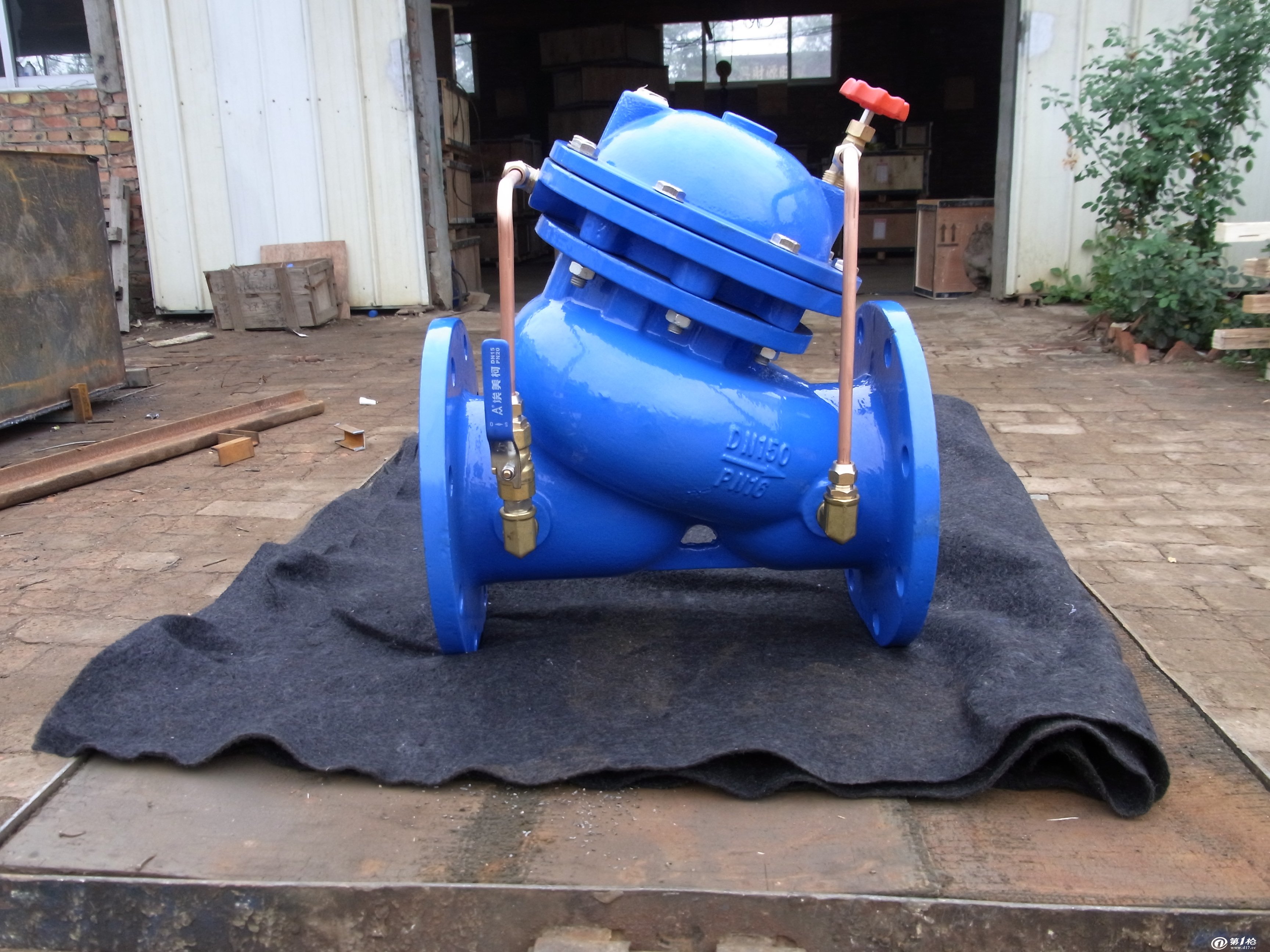
The overall size of the valve is comparable to that of an ordinary check valve and consists of the main valve and external accessories. Among them, the main valve includes valve body, pressure plate and diaphragm, large valve plate, slow closing valve plate, valve seat, stem assembly and other components. The slow closing valve plate is connected to the pressure plate and diaphragm with the stem assembly, the diaphragm is pressed between the valve cover and the diaphragm seat, and the up and down movement of the diaphragm drives the slow closing valve plate up and down.
The valve stem passes through the center hole of the large valve plate, so the large valve plate can slide along the valve stem within a certain range. Normally, the big valve plate is pressed on the valve seat by its own weight, so that the valve is in the closed state. Multifunctional pump control valve external accessories installed on both sides of the valve diaphragm and valve inlet and outlet pipe, the lower chamber of the diaphragm and the valve inlet side of the connecting pipe is equipped with control valves, filters, and a special backstop valve.
The upper cavity of the diaphragm and the valve on the outlet side of the connection pipe is only equipped with a filter and a control valve. The movement and position of the large valve plate and the slow closing valve plate in the main valve determine the change of the valve's working status and opening and closing. The valve's external accessories and piping at any time before and after the valve pressure changes to the valve by the diaphragm divided into the upper and lower chambers, control the movement of the large valve plate and slow closing valve plate, and can be adjusted through the accessories to change the large valve plate and the slow closing valve plate speed, so that the valve's opening and slow closing time in the specified range.
Working Pressure
This type of multifunctional control pump valve working pressure 1.0MPa, 1.6MPa, 2.5MPa, 4.0MPa, 6.4MPa, 10.0MPa six, the action pressure is greater than or equal to 0.03MPa, the media temperature in 0-80 ℃, slow closing time can be adjusted in 3-120s, the pipeline flow rate of 2m / s pressure loss of less than 0.01MPa, the peak of water hammer is less than 1.5 times the working pressure, nominal caliber DN50-DN1400. Pipeline flow rate of 2m/s when the pressure loss is less than 0.01MPa, the peak value of water hammer is less than 1.5 times the working pressure, nominal caliber DN50-DN1400.
Product Parameter
|
DN |
L |
H |
D |
D1 |
D2 |
n-Φd |
|||||||||||
|
PN1.0 |
PN1.6 |
PN2.5 |
PN1.0 |
PN1.6 |
PN2.5 |
PN1.0 |
PN1.6 |
PN2.5 |
PN1.0 |
PN1.6 |
PN2.5 |
||||||
|
40 |
240 |
395 |
150 |
150 |
150 |
110 |
110 |
110 |
84 |
84 |
84 |
4-18 |
4-18 |
4-18 |
|||
|
50 |
240 |
395 |
165 |
165 |
165 |
125 |
125 |
125 |
99 |
99 |
99 |
4-18 |
4-18 |
4-18 |
|||
|
65 |
250 |
405 |
185 |
185 |
185 |
145 |
145 |
145 |
118 |
118 |
118 |
4-18 |
4-18 |
8-18 |
|||
|
80 |
285 |
430 |
200 |
200 |
200 |
160 |
160 |
160 |
1132 |
132 |
132 |
8-18 |
8-18 |
8-18 |
|||
|
100 |
360 |
510 |
220 |
220 |
235 |
180 |
180 |
190 |
156 |
156 |
156 |
8-18 |
8-18 |
8-22 |
|||
|
125 |
400 |
560 |
250 |
250 |
270 |
210 |
210 |
220 |
184 |
184 |
184 |
8-18 |
8-18 |
8-26 |
|||
|
150 |
455 |
585 |
285 |
285 |
300 |
240 |
240 |
250 |
211 |
211 |
211 |
8-22 |
8-22 |
8-26 |
|||
|
200 |
585 |
675 |
340 |
340 |
360 |
295 |
295 |
310 |
266 |
266 |
274 |
8-22 |
12-22 |
12-26 |
|||
|
250 |
650 |
730 |
395 |
405 |
425 |
350 |
355 |
370 |
319 |
319 |
330 |
12-22 |
12-26 |
12-30 |
|||
|
300 |
800 |
760 |
445 |
460 |
485 |
400 |
410 |
430 |
370 |
370 |
389 |
12-22 |
12-26 |
16-30 |
|||
|
350 |
860 |
840 |
505 |
520 |
555 |
460 |
470 |
490 |
429 |
429 |
448 |
16-22 |
16-26 |
16-33 |
|||
|
400 |
960 |
910 |
565 |
580 |
620 |
515 |
525 |
550 |
480 |
480 |
503 |
16-26 |
16-30 |
16-36 |
|||
|
450 |
1075 |
1030 |
615 |
640 |
670 |
565 |
585 |
600 |
530 |
548 |
548 |
20-26 |
20-30 |
20-36 |
|||
|
500 |
1075 |
1135 |
670 |
715 |
760 |
620 |
650 |
660 |
585 |
582 |
609 |
20-26 |
20-33 |
20-36 |
|||
|
600 |
1230 |
1270 |
780 |
840 |
845 |
725 |
770 |
770 |
685 |
682 |
720 |
20-30 |
20-36 |
20-39 |
|||
|
700 |
1650 |
1460 |
895 |
910 |
960 |
840 |
840 |
875 |
794 |
794 |
820 |
24-30 |
24-36 |
24-42 |
|||
Main installation dimensions: (unit:mm)
Related PRODUCTS
RELATED NEWS
Y Type Strainers: A Comprehensive Guide
Y type strainers are crucial components in various piping systems, known for their ability to filter out impurities effectively.
Understanding Water Valve Options for Your Needs
When it comes to managing water flow in plumbing systems, knowing the various valve types available can significantly enhance functionality and control.
Functions and Types
Understanding the various types of water valves in your plumbing system is crucial for efficient management and maintenance.


